Service Configuration
Overview
When session instantiation is required we want to remove the assumption that all the needed code is already present and configured on the nodes along the service path. This aspect is really important when devices with limited capabilities, which could benefit of this support to download code only by need, are considered; nevertheless this is an important aspect also for more powerful machines, for example when we log on a machine for the first time we would like to access our services and applications without the need of time consuming and error prone configuration operations.
The main idea of service configuration (represented in Figure 1) is to send a MA, i.e., the Plan Visitor Agent, PVA, to activate and configure all the active proxy components within the service path.
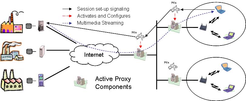
Figure 1: Configuration Service Scenario.
Requirements
The requirements on which the configuration service was built are the following:
- Flexibility: we want to design the middleware in a way that lets the usage of standard C/S based application components without moving capabilities for the realization of more dynamic services.
- Location awareness: the service will configure the distributed components taking into account location considerations.
- Layering: an important requirement is keeping the application deployment separated from the middleware deployment, that is not trivial when multimedia services are considered. In particular, one major concern was dividing the functional aspects of the multimedia service, such as the streaming control, that are treated at the application layer, from non-functional ones, like resource booking and monitoring, configuration/reconfiguration management and mobility management, treated at the MW layer.
Architecture The proposed solution joins standard C/S basic mechanisms and MA based higher level facilities. The solution proposed for the service configuration includes also static resource management (resource negotiation and booking), but we will consider this part of the service separately, when we present QoS Management.
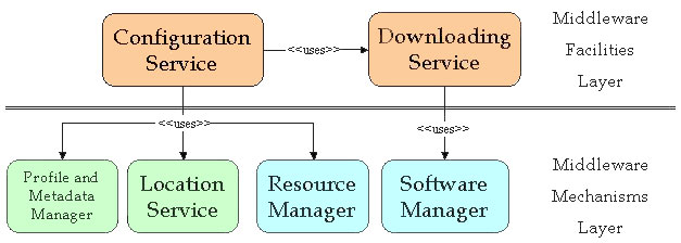
Figure 2: Configuration Service Architecture.
Figure 2 presents a first high level view of the architecture that highlights the service layering and the different modules that compose the configuration service. The green modules are based on standard C/S solutions, they are present on all the nodes participating in the architecture, but they all interrogate centralized servers. The blue ones instead represents services that run on each node, and do not communicate with any external server. Finally the orange ones are partially or totally based on mobile agents. In fact the MAs were applied to the aspects that are more dynamic, and that could require more flexibility, also in changing at the runtime the strategies, for example the strategies applied for the downloading of the code within the distributed architecture are encapsulated in a MA.
Moreover the figure underlines the use relationships that incur between the different modules.
Mechanisms Layer Design and Implementation Hints
Profile and Metadata Manager
This mechanism is used to store user profiles. In the first version of MUM the architecture was a simple client/server solution. A centralized server maintained all the profiles in a co-located database. A similar solution was adopted to store presentation metadata. MUMOC evolves this simple architecture by decentralizing the metadata service.
Location Service
This service is strongly based on the location abstraction introduced by SOMA environment, reported in figure 4, that is a tree. In particular, the core of the network consists of a set of fixed hosts interconnected by wired broadband LANs; these hosts are interconnected in an overlay network logically organized as a tree.
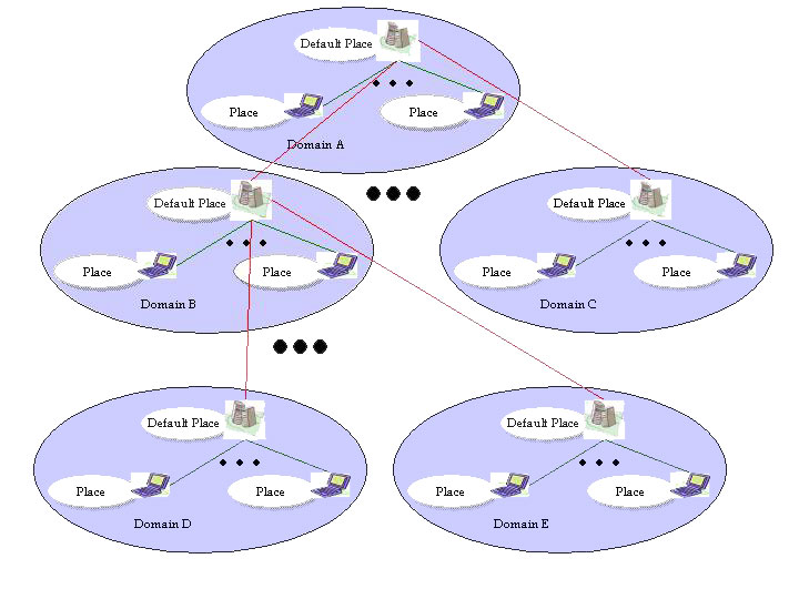
Figure 4: Soma location abstractions.
MUM enriches SOMA by introducing a new abstraction, i.e. the Path, that is the path from the highest node in the tree to the internal nodes or to the leaves, and locates them. Therefore, available location abstractions are: tree, leaves, and paths connecting nodes one another. Client terminals, with possibly differentiated (and limited) local resources, access the core overlay either via wired or wireless connectivity; they are the leaves of the VoD distribution tree. Distance between MUM nodes is measured in terms of the number of hops to navigate the tree, while localities are mapped into sub-trees.
Resource Manager
The Resource Manager is a service that acts locally on each node, encapsulating resource negotiation and brokerage. To have more information about this service see the page about QoS Management.
Software Manager
The Software Manager is present on each node and acts locally offering to the upper layer the functionalities. It is composed of two parts. The Software Repository lets the upload and download of the needed code in a repository, the Component Manager instead memorizes the components that are active.
In fact, if a video server was activated on a certain node, the Component Manager, that is part of the Software Manager, memorize its endpoint. Thus, when a Plan Visitor Agent during the configuration process arrives on that node to configure the server, it first asks to the Component Manager if the server is already initialized, and this activation is saved.
We want to stress that, following the layering requirement fixed above, this service realize only the saving mechanism, without encapsulating any strategy.
Facilities Layer Design and Implementation Hints
Downloading Service
An event based infrastructure was implied to let a Java object to require component download. This support, in case the code is not present on the node, launch an agent called Download Agent that encapsulate the strategies and waits that this agent came back saving the required software. After that, the support fires an event to advise the client of this service that the download process was completed.
In figure 5 we represented, using a UML-like notation, a collaboration diagram that highlight the service design and the implied protocols. The "A" means Mobile Agent, the static components are blue, the mobile ones are yellow, while the SOMA place are green.
Figure 5: Downloading Service Collaboration Diagram
So far we have implemented a first simple strategy. If the request come from a default place the Download Agent simply downloads the required components on the default place, while if it comes from a simple Place, the Download Agent downloads the required components first to its default place, then to the place itself.
Configuration Service
This service realizes both the QoS negotiation/booking (interacting with the Resource Manager) and the configuration of the distributed service. There are two middleware components (MC) on which this service stands: the Decision Maker (DM) and the Plan Visitor Agent (PVA). In figure 2 the scenario considered for the configuration process is presented.
The Decision Maker, realized as an object without moving capabilities, encapsulates the strategies to decide how to configure the Service Path. It gets, using the services offered by the Mechanisms Layer, information about the user profile, the position of the current node within the distributed system, and the metadata about the presentation the user is interested in. Then it elaborates this information returning a Plan that contains one or more solutions corresponding to different QoS levels for the same presentation, as shown in figure 6.
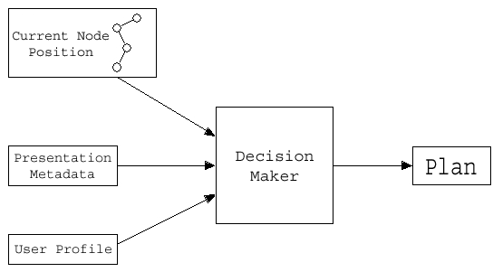
Figure 6: The construction of the Plan.
Each solution specifies the necessary actions to take for service path configuration, and the necessary resources. For example the first implemented solution took into account a locality principle, therefore the Plan was built choosing, for the required title, the best N presentations nearest to the client. Besides, for each presentation there is a metadata which fixes the resources needed for its playing. Finally the Plan contains the descriptors of the components that the PVA must configure along the service path.
The Plan Visitor Agent instead is an MA that moves along the service path configuring it. In fact, once the configuration service has obtained the Plan from the DM, passes it to the PVA that goes through the path from the Client to the Server negotiating and booking the resources, initializing and configuring the Application Components, ACs, and their corresponding MCs. In every node that participates to the architecture, after the PVA has arrived, it asks if there are enough resources for the first configuration contained in the Plan, and, if there are, it books them and instantiates another PVA, which is sent forth. It is necessary to leave the PVAs on the nodes participating in the service delivery because, to finish the configuration of a component on a certain node, the PVA has to wait the endpoint of the next component along the path, that is sent back by the next PVA. Figure 7 represents a detailed collaboration diagram that refers to the configuration process.
Figure 7: Configuration Process Collaboration Diagram
If there are enough resources in the system, the service path is established and the service delivery begins, otherwise a configuration trace back is done. The configuration trace back begins when the PVA does not succeed in booking the resources; afterwards it checks if it owns another configuration (at a lower QoS level). If there are enough resources for this second one the configuration process continues, otherwise a message is sent back to the previous PVA, to ask if it has got an alternative configuration. This is what we mean with configuration trace back. Figure 3 shows the used components and protocols employed in the configuration process, and in the final version it will be explained in detail.
The usage of MA paradigm facilitates the implementation and test of different strategies, moreover it was easy to implement the protocols between the PVAs (for example to exchange the information about the endpoint) using the communication facilities offered by SOMA.
Finally for the design of the PVA it was used the Pattern Visitor, where the PVA is the visitor and the Plan offers a method to accept its visitor, i.e., to let the visitor execute its Plan.
References
- P. Bellavista, A. Corradi, L. Foschini, "MUM: a Middleware for the Provisioning of Continuous Services to Mobile Users", Proceedings of the 9th IEEE International Symposium on Computers and Communications (ISCC'04), Alexandria, Egypt, June 29-31, 2004, IEEE Computer Society Press.
|