The MACHINE Double-Layered Architetcure

|
The MACHINE Double-Layered Architetcure |
|
To better understand the motivations behind MACHINE architecture, let us rapidly introduce which kind of operations should be taken into account by an advanced support for runtime change of interface/connector (handover management). It is possible to identify two major phases in handover procedures: Evaluation Process and Continuity Management.
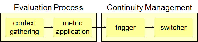 Handover Management facilities include Evaluation Process and Continuity Management. The figure below represents how the MACHINE middleware is logically organized. At the current stage of prototype implementation, we have primarily focused on the evaluation process phase, while the continuity management layer is part of our current work. 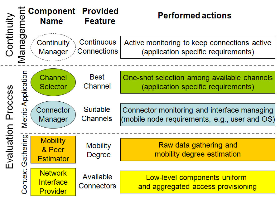 MACHINE logical organization. The Context Gathering layer consists of the Network Interface Provider (NIP) and the Mobility & Peer Estimator (MPE) components, which are the primary context sources in MACHINE. NIP provides a uniform and aggregated access to underlying network interfaces, e.g., by providing the set of available connectors for each interface; MPE determines mobility state for client nodes and connectors, e.g., whether a client is currently still or mobile. The Metric Application layer is composed by Connector Manager (CoM) and Channel Selector (ChaS) that respectively evaluate connectors and channels. CoM identifies the list of suitable chanels depending on the whole client node requirements; ChaS selects the most suitable channel in the CoM-provided list by additionally considering application-specific requirements. Let us note that the figure below not only points out each MACHINE component role, but also delineates the associated abstraction layer: MIP provides information about available connectors; MPE is at a slightly higher abstraction level and exploits NIP output to dynamically evaluate client node and connector mobility degree; CoM interacts with connectors to estimate their suitability for realizing reliable and durable channels; ChaS evaluates CoM-provided channels to select the best one for each application. The figure below presents how we have implemented the model in the actual MACHINE architecture. Differently from the purely layered model, MACHINE sometimes adopt a cross-layer solution for the sake of performance: NIP behaves as input for both MPE and CoM; MPE is configured by CoM in a feedback fashion; moreover, each MACHINE component not only provides its features and information to other middleware components, but also to the application layer. In this manner, MACHINE is able to behave both as an autonomous and self-contained system providing the most suitable channel and as a support component useful for other support infrastructure, e.g., our future middleware for continuity management built on top of MACHINE. In any case, a clear distinction between context gathering and metric application is ensured. 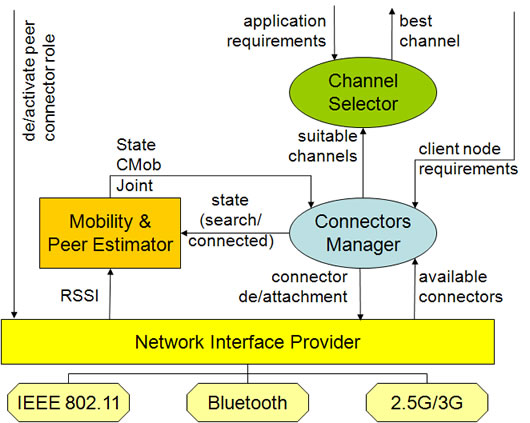 MACHINE architecture. |
||
| 9-nov-09 |